|
Project - Turn-out Feedback
When controlling a layout without any digital system, meaning analogue, it is really good to have some sort of feedback to see how all switches (points) are set. The following method works for both analogue and digital, and with just push-buttons or via a graphic switchboard.
This description will show how to arrange switch feedbackindependent of type of control system. The difference is just in what receives the switch signal, direxctly to the switch or to the digital switch decoder.
To make this work, there must be some sort of travel end switch connected to the switch motor. Such a switch will break the circuit when the plunger has come to its end position and thus break the current. This will make the plunger stay in that position. At the same time the other end switch will close its circuit so that next time a switch signal arrives, the magnetic plunger will be pulled over to the other end and stay there - the switch is turned.
It looks something like below. (Green button for straight ahead and red for turn out.)
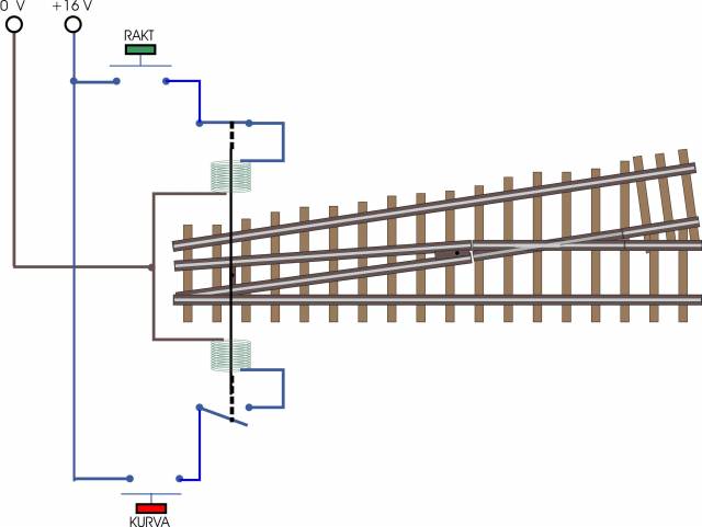
If the green button "RAKT" (straight ahead) is pushed, the coil get current. If theb other, red button, is pushed nothing happens as that curcuit is broken. We will make use of this by connecting an LED and a resistor to indicate which of the two coils that can allow a current flow. This is done by using the opposite colour depending on which coil is active. See picture below.
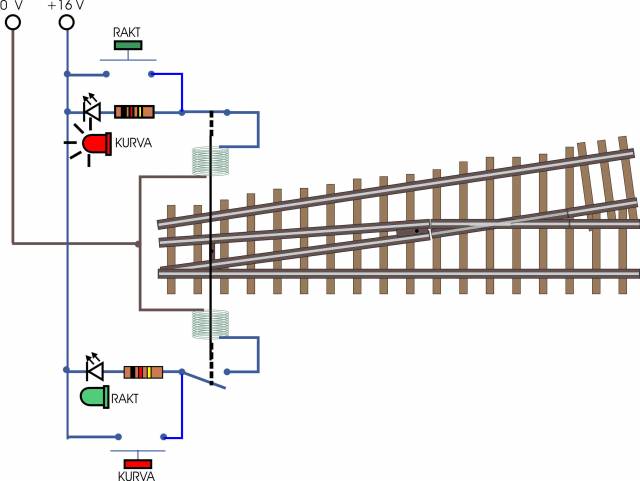
This works on any analogue track and the following parts are used for each switch (point):
- A red LED for 3 Volt (3 or 5 mm as desired)
- A green LED för 3 Volt (as above)
- Two resistors of 2000 Ohm (2kOhm), 0,25 W at 16 V.
- Kabel.
(Note that the resistor is placed on the feed side of the LED.)
To make a graphic switchboard using the above solution youn only need to fit a pair of push buttons at each switch on the graphic panel. See below where the buttons are placed on the panel instead of by the switches.
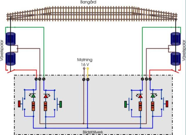
This way the cabling goes from the graphic switchboard to the switches instead of from switch blocks. Use either two push buttons or one lever switch to give a switch pulse. The LEDs are placed on the switchboard together with the buttons for the respective switch. It could then look like below.
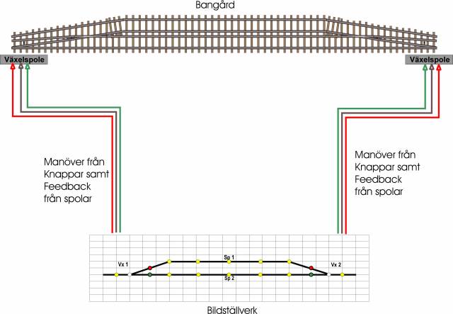
I choose lever switches and the red and green dots are the LEDs. The yellow dots/LEDs will show which track has been selected just like on any real switchboard.
If we want to do the same thing for a digitally controlled layout it will look like below. The feedback unit, panel communication unit, control unit, and computer are all connected to a data bus. The cabling to the switches goes to the control unit and the graphic switchboard is fed from the feedback unit and feeds the control unit. The presentation on the graphich switchboard is fed from the panel unit.
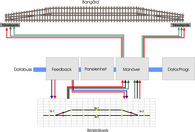
This way it becomes possible to control a digital layout both manually via a graphic switchboard or via the digital control program.
The graphic switchboard for Dåseberga is described more closely in the file named SDJ Graphic Switchboard.
/Peter
|